

Home>Let's start things with IC 555
Let's start things with IC 555.
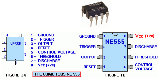
IC IC NE555 is too many too many applications, electronic civil nobody is unaware of this IC. 555 has 8 legs, diagram shows the use of the foot under the following names:
Pin 1 (GND): Legs for masse to take the line connected.
Legs 2 (Trigger): Legs than the standard voltage is applied at 1/3 the power supply.
Legs 3 (Output): Leg recliner, feet 3 c1 signal on pulsed, not at low pressure at high pressure.
Legs 4 (Reset): Chan established state pressure on the foot thinking at a low 3, or operations.
Legs 5 (Control Voltage): Chan alter the standard applied in the IC 555.
Legs 6 (Threshold): Legs over the standard voltage is applied at 2/3 the power supply.
Legs 7 (Discharge): Legs with locking shut masse, often used for capacitors to discharge.
8 feet (VCC): Legs on the road connecting the source V +. IC 555 to work with the sources from 3 to 15V.
Figure 1: Shows the order of the pins of the IC 555.
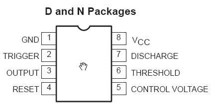
Figure 2: Shows that mimics schematic of the IC 555. (If you want to simulate IC 555 in the PSpice, you can use this diagram, describing the command Subcircuit then distilled into a library named 555 and after You use it to run the simulation of circuit with IC 555 format).
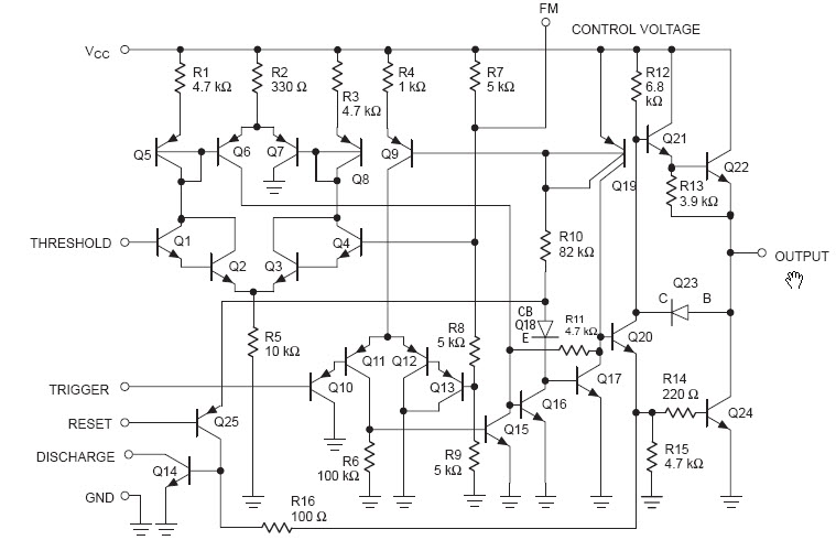
Figure 3: Shows the block diagram of the IC function IC 555. In connection with the first leg and foot 8 masse source connected to Vcc line, a bridge voltage divider resistors equal to 3 (are 5K). This creates pressure for dividing 2 level threshold voltage, the third one is used as a source of pressure applied to the floor against pressure threshold, the input signal on the second leg, and the other one is used as the source voltage level 2/3 level voltage threshold voltage than other floors, the input on pin 6. pin 5 may be affected in addition to altering the threshold voltage. Pin 7 is an electric lock / off (transistor saturation / stop led) by the pressure on the leg 3. Leg 3 is leaned out and was leaning out a Flip Flop floor, so the signal is pulsed on leg 3 (the pressure is only set at high or low status). Reset 4 foot legs, while low pressure vacuum at its 4 feet 3 pins are always at low pressure, just as the foot 4 at high pressure, then the pressure on the foot status 3 floors will follow the impact of Flip Flop .
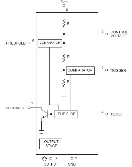
Figure 4: Note that in this circuit, connector pins No. 2 to No. 6. IC 555 legs were assembled into oscillation circuit (A-Stable). Frequency pulses on pins 3 will depend on the value of the resistor RA, RB and capacitor C. On foot 5, with the addition 0.01uF filter capacitors to stabilize the voltage of the voltage threshold levels. Status on leg 3 will depend on the high level of pressure on the foot 4 and the low pressure oscillations on foot 4 (pinned at a low level).
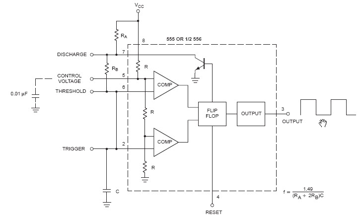
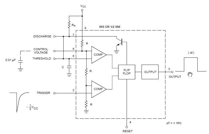
Figure 5: IC 555 to be assembled into multi comedy circuit monostable (Mono-Srable), where the pressure on the legs 3 will depend on the pressure at the foot of leaning on the pressure on the foot 2. When 2 to under pressure 1/3 Vcc voltage threshold, the amount of leaning out over 3 feet high pressure will increase. Pulse in on foot 2 may be in continuous (analog), but output on pin 3 is always in the form of pulses (or digital form), established only at high or low voltage. Therefore, IC 555 is a combination of two types of signal A / D (Analog / Digital).
Some common applications of the IC 555.
The drawing shows the use of the pins of an IC 555.
Application 1 : How to assemble multi comedy monostable circuits, pulse to pulse out on foot on foot 2 and 3 of the IC 555.
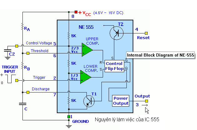
The drawing shows in IC 555 has 2 levels compared pressure. Floor over pressure below (LOWER COMPARATOR), the voltage on the pressure on the legs 2 for comparison with the threshold voltage is (1/3) Vcc, leaning out of the AP story on the impact of the Flip Flop Set foot. Pressure on the floor against (UPPER COMPARATOR), input voltage on foot 6 for comparison with the threshold voltage is applied (2/3) Vcc, output of the floor leaning against the foot pressure on the impact of the Flip Flop Reset. Such status of Flip Flip leaning out will depend on the impact of the input signal on pins 2 and 3 feet.
* If the pressure falls below 2 feet (1/3) Vcc is reclining on a 3 foot high pressure will increase.
* If the pressure on the higher 6 feet (2/3) Vcc lean out on foot to $ 3 will depressions.
* When the foot 3 at high pressure, the transistor T1 will stop leads (pins 7 acts as the openings masse).
* 3 When vacuum at low pressure, the transistor T1 will saturate (acts as the connector pins 7 masse).
* Reset Leg 4 feet. When 4 feet at low pressures, vacuum 3 was pegged at a low pressure, just as the foot 4 at high pressure, then 3 feet can vary with Flip Flop. Hence in the oscillation circuit, it is common to 4 feet tall connected to the source.
Application 2 : The circuit uses rapid testing of IC 555.
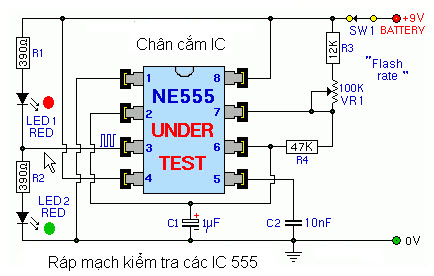
This is the oscillator, pulse frequency on leg 3 depending on the power factor value of R3 (12K), VR1 (100K), R4 (47K) and capacitor C1 (1uF). When the oscillation circuit, the pressure on the legs three times higher at low, and LED2 and LED3 blinks. Because the circuit uses IC socket, so if you want to try to quickly connect the IC to the circuit IC, if 2 Led blinking is a sign that good IC. Conversely, if two non-blinking LED on the IC circuit is damaged. VR1 user to adjust the clock frequency.
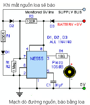
Application 3 : Circuit reported lost by the audio signal source.
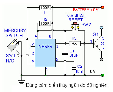
Application 4 : Use a mercury switch as sensors to detect the investigation.
When the circuit is powered. Capacitor C1 (0.1uF) will set foot 4 at low pressure, this ensures foot 3 will be at low pressure, after a while, capacitors C1 through line load R2 (100K) to a high pressure, vacuum pressure level 4 high, IC 555 will now work on the state.
Due to 6 feet always interesting pin voltage level, at which point if the sensor is open circuit Electronic mercury (it does not do research), pins 2 through R1 (100K) is set at a high pressure, should foot 3 will still at low pressure. If mercury Electronic closed because it is working, then the leg 2 is pulled down to the low voltage (by touching masse) and this time will be up to 3 feet high pressure. People use to transistor Q1 opens external control devices.
Application 5 : Using the optical or electronic eye LDR to do, detect light rays.
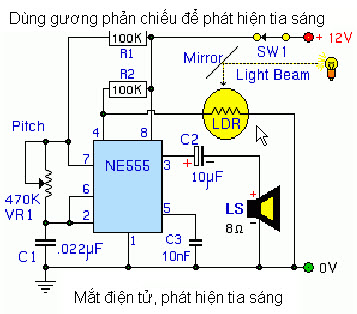
IC 555 into oscillation circuit assembly, output on 3 legs will stimulate LS speakers emit howls. Frequencies adjusted by rheostat VR1 (470K).
* If there are rays of light streaming through reflector optic effect or click on LDR, this time the internal resistance of the fiber becomes small, 4 feet are set at low pressure, should be pegged at 3 feet low pressure, the speaker does not emit sound .
* If the loss of the optical beam shines or LDR, the internal resistance of the LDR increases optical return, it set up a 4 foot high pressure (due to the effect of pressure hanging resistor R2), the circuit will oscillate and emit LS speaker light signal loss.
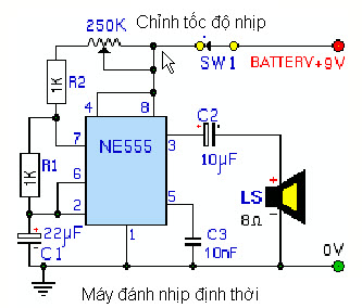
Application 6 : Circuit ticking timer.
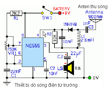
Application 7 : The circuit detects electromagnetic waves.
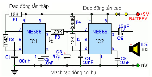
Application 8 : Circuit creates a siren (2 beats).
Application 9 : You order a logic probe assembly.
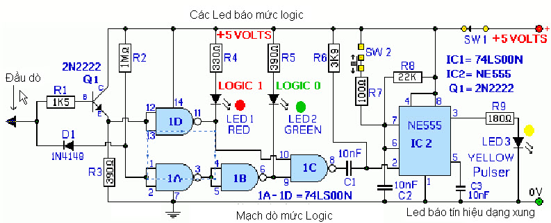
Application 10 : Control without using infrared light.
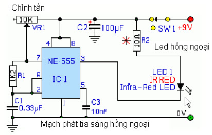
* Circuit signaling format infrared light.
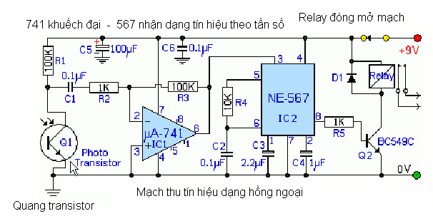
* The circuit format reception infrared light .
Application 11 : Lamp signal (flashing lights),